Signal Processing: Filtering
The Fourier Transform is extensively used in the field of Signal Processing. In fact, the Fourier
Transform is probably the most important tool for analyzing signals in that entire field.
So what exactly is signal processing? I'll try to give a one paragraph high level overview.
A signal is any waveform (function of time). This could be anything in the real world - an electromagnetic
wave, the voltage across a resistor versus time, the air pressure variance due to your speech (i.e. a sound wave),
or the value of Apple Stock versus time. Signal Processing then, is the act of processing a signal to obtain
more useful information, or to make the signal more useful.
How can a signal be made better? Suppose that you are listening to a recording, and there is a low-pitched hum
in the background. By applying a low-frequency filter, we can eliminate the hum. Or suppose you have
a digital photograph, and it is very noisy (that is, there are random specs of light everywhere). We can
use signal processing and fourier transforms to filter out this undesirable "noise".
How exactly does the signal processing or filtering work? I'm glad you asked. We'll start by looking at
common input-output systems, known as Linear Time-Invariant (LTI) systems
[also known as Linear Shift-Invariant (LSI)].
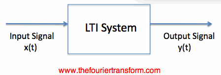
Suppose we have a box that accepts an input signal and produces an output signal from that. Such a box
can be thought of as a system:
Figure 1. A System which takes an input signal and produces and output signal.
The box of Figure 1 could be anything. Examples are given below:
Linearity. An LTI system must be linear. To define this, suppose an input signal x1(t) produces an
output y1(t), and another signal x2(t) produces the output y2(t). Then the system is linear if the sum of the
two input signals produces the sum of the two output signals. That is, if x1(t)+x2(t) is the input signal, the
output must be y1(t)+y2(t). This must be true for every possible input signal.
Time (Shift) Invariance. An LTI system must be time-invariant. Suppose a signal x(t) applied to
the system produces
an output y(t). Then the delayed version of the signal, x(t-c) (where c is some real number), must give
an output equal to y(t-c). Loosely speaking, this means the system doesn't care when the input is applied,
the result is always the same.
These two requirements define LTI systems. They are not very restrictive, so LTI system theory is very general
(although definitely not every system is linear and shift-invariant). On this broad class of systems, we
will now discuss filtering.
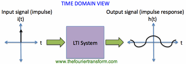
Before we jump into filtering, I'll have to give some background on LTI system analysis. The fundamental
way to describe the response of an LTI system is via the impulse response. That is, we use
the impulse function
as the input signal and view the corresponding output signal, known as the impulse response.
Why is the impulse used? The answer again comes from Fourier Transforms:
the Fourier Transform of the impulse is a constant with respect to frequency.
This means that if the input is an impulse function in time, we are essentially sending equal energy
at all frequencies. That is, in the frequency domain, the energy density is the same at every frequency.
As a result, when we view the Fourier Transform of the output, we now know how the system reacts
to every possible frequency. The reason for this goes back to the
linearity of the Fourier Transform:
the impulse in time can be thought of as an infinite
sum of sinusoids at every possible frequency. The output result then is the sum of the responses to each
frequency. [Side Note: The output of an LTI system due to a single frequency input will
have only the same single frequency in the output signal. This is a consequence of the time-invariance property.
The signal can be scaled in magnitude and phase delayed, but the frequency cannot change].
Hopefully a couple figures can clear this up if it is cloudy. Figure 1 represents
the time-domain view of the LTI system. That is, an impulse is used as the input signal, i(t),
and the output signal h(t) is observed:
Figure 1. Time-Domain View of LTI System.
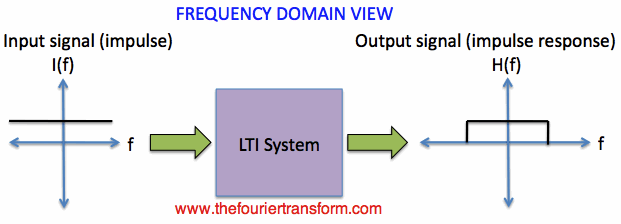
Equivalently, we can view the above signals and system in the frequency domain. By taking
the Fourier Transforms of the input and output signals, we see that a constant input signal [I(f)=1]
gives rise to the output H(f), which is the frequency response, in Figure 2:
Figure 2. Frequency-Domain View of LTI System.
Note that H(f) of Figure 2 is in general a complex number.
If he impulse response of a system is written as h(t), then the Fourier Transform of the impulse
response is H(f), and is also known as the Transfer Function. This Transfer Function describes
what the system does to every frequency (i.e. the amplitude and phase changes).
In the next section, we'll describe frequency filters using the transfer function.
LTI Systems
What are the restrictions on an LTI system? Input Output A Bit of System Theory
Next: Frequency Filters
Fourier Transform Applications
The Fourier Transform (Home)